

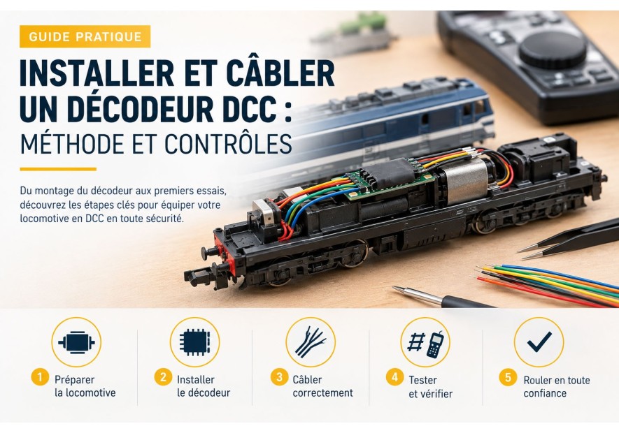

Installing and wiring a DCC decoder: method and checks
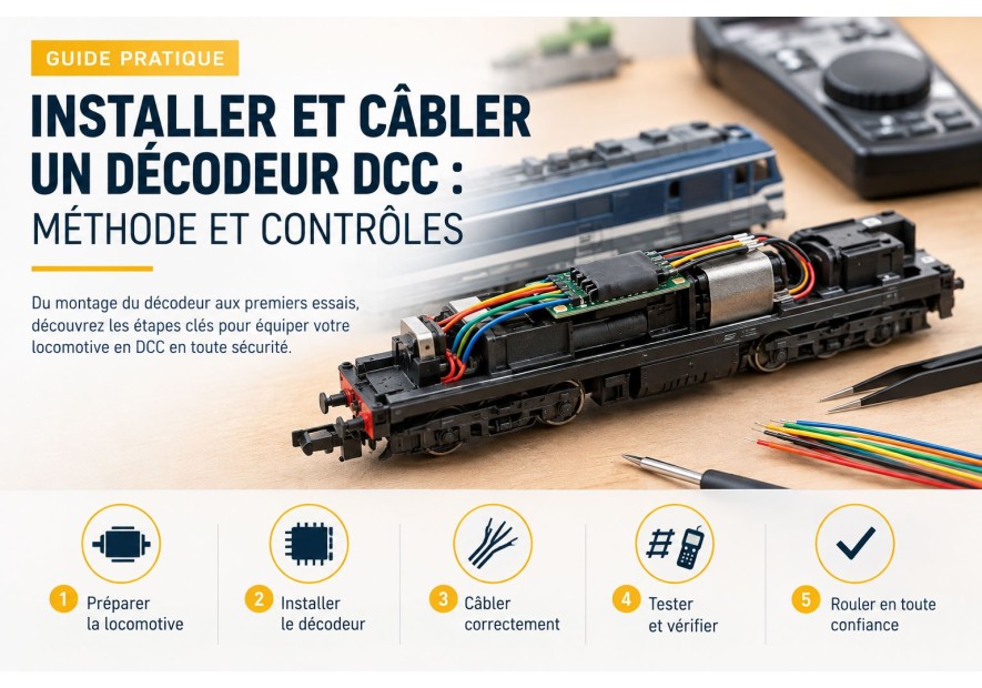
How to install and wire a DCC decoder in a locomotive: NEM sockets, wires, testing and programming.
Installing a DCC decoder starts by identifying the locomotive interface. NEM 651, NEM 652, 21MTC, PluX22 and Next18 are not interchangeable without suitable hardware. This guide also explains how to proceed when a locomotive has no NEM socket.
Identify the socket before buying
Check the manual or circuit board. NEM 651 has 6 pins, NEM 652 has 8, NEM 660 has 21, NEM 658 is PluX22 and NEM 662 is Next18.
- ESU 59020: NEM 652, 8-pin DCC decoder.
- ESU 59626: NEM 651 with wires.
- ESU 59629: 21-pin NEM 660.
- ESU 59622: PluX22.
- ESU 59828: Next18.
Installing a decoder in a locomotive without a NEM socket
An older locomotive or a non-standard circuit board can still be converted, provided that the motor is isolated and every conductor is identified. Work with the power off, use a fine soldering tip and photograph the original wiring first.
1. Identify the connection points
Separate the two rail pickups, the two motor wires and the lighting wires. The metal chassis must not remain connected to a motor output or function output unless the decoder documentation explicitly allows it. Use a continuity tester to check grounds and shorts.
2. Isolate the motor
Before connecting the decoder, make sure neither motor terminal is electrically connected to the chassis. Remove or cut suppression capacitors only when recommended by the decoder manufacturer. Secure the decoder with insulation without blocking moving parts.
3. Respect each wire function
| Function | Connection | Check |
|---|---|---|
| Right rail | Matching rail input | No continuity with left rail |
| Left rail | Second rail input | No short between rails |
| Motor | Both motor outputs | Motor isolated from chassis |
| Lighting | Function outputs and return | Respect polarity and current |
Colours never replace the decoder diagram. ESU 51940 to 51949 wires are available in 10-metre lengths and several colours for organised wiring:
- ESU 51940 white · 51941 violet · 51942 black · 51943 red · 51944 orange
- ESU 51945 green · 51946 grey · 51947 yellow · 51948 brown · 51949 blue
4. Test before closing the body
- Check every connection with the power off.
- Place the locomotive on a programming track.
- Read the decoder address without starting the motor.
- Test forward and reverse at low speed.
- Test each light separately and monitor abnormal heat.
The ESU 53900 tester checks a decoder outside the locomotive. The ESU LokProgrammer reads and programs its settings.
When should you add a socket?
If you want the decoder to be replaceable, add a suitable interface such as the ESU NEM 651 socket. Identify every wire before fixing it and leave enough slack to remove the body. For complex or older locomotives, have the wiring checked by an experienced modeller.
Key points
The reliable sequence is: identify the interface, isolate the motor, identify the rails, wire the outputs, test at low speed and program the decoder. See our DCC compatibility guide.
